Appearance
TMR3109 Magnetic Encoder, End to End: Protocol, Driver, Calibration, and One "Wrong Magnet" Pitfall
The TMR3109 is a 23-bit magnetic rotary encoder that reads absolute angle over SPI and sits on the gripper finger's rotation shaft to measure opening. The whole chain is live, from driver and data acquisition to calibration: the MCU samples at 50Hz → AP → nine-point piecewise calibration in the web UI. The biggest lesson isn't in the software: the number-one cause of bad readings isn't off-centre assembly, it's a magnet installed with the wrong magnetization direction.
Results at a Glance
After swapping in the correct magnet, the range recovered from "single digits to the low twenties, with 10× spread between units" to ~40°:
| Capability | Status |
|---|---|
| Protocol parsing | SPI Mode 1, 28-bit frame (23-bit angle + CRC + error) ✅ |
| Sampling | MCU at 50Hz → shared memory → AP → web UI / calibration ✅ |
| Calibration | two-point linear + nine-point piecewise coexist (fixture at 0/5/…/40°) ✅ |
| Readouts | chip angle / calibrated angle / opening percentage / range — four views ✅ |
| Failure modes | magnet type, sensor offline, missing magnet, degraded range — all covered by diagnostics ✅ |
Sensor and Mounting Requirements
The TMR3109 (MultiDimension) is based on tunnel magnetoresistance: the chip measures the direction of the magnetic field vector directly above it, not the angle of a part. The magnet rotates with the finger shaft, the in-plane field vector follows it, and the chip reads out an absolute angle.
The vendor's hard mounting requirements (product datasheet §3.6):
| Item | Spec |
|---|---|
| Magnet | Ø9 × 2.5 mm, NdFeB N35SH, diametrically magnetized |
| Mounting distance (air gap) | 1 ~ 3 ~ 10 mm |
| Field strength at the chip surface | 100 ~ 1000 Gs |
| Centre offset | ≤ 0.5 mm |
| Centre tilt | ≤ ±3° |
⚠️ The field-strength range is stated two different ways: §3.6 of the datasheet says 100~1000 Gs while the product page says 200~800 Gs — worth confirming with the vendor.
⚠️ The Number-One Prerequisite: the Magnet's Magnetization Direction (the Star of This Page)
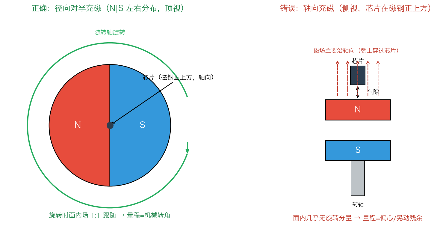
"Diametrically magnetized" is literally what it says: the disc's N and S poles sit left and right along a diameter. What this batch of assemblies had was axial magnetization (one circular face is N, the other is S) — and that's where the disaster starts:
Driver and Data Path
SPI Protocol and Bit Extraction
The read-angle command returns 28-bit data (a 4-byte SPI frame, MSB first):
| Bits | Content |
|---|---|
| d[27:5] | 23-bit angle code |
| d[4:1] | 4-bit CRC (x⁴+x³+x²+1, init 0011) |
| d[0] | error bit |
c
// 换算:θ = raw / 8388608 × 360°(raw 为 23-bit 角度码)
rt_uint8_t tx[4] = {0x60, 0x00, 0x00, 0x00}, rx[4] = {0};
spi_xfer(s, tx, rx, 4);
uint32_t v = (rx[0]<<24) | (rx[1]<<16) | (rx[2]<<8) | rx[3];
uint32_t raw = (v >> 5) & 0x7FFFFF;      // d[27:5]
float angle = raw / 8388608.0f * 360.0f; // 0~360°Gotcha: the datasheet timing diagram doesn't say so, but measured MISO has a 4-clock pipeline delay — extracting the bits exactly as the manual aligns them clamps the reading to 337.5°–360°. The code above is corrected to match the measurement (
>>5to take d[27:5]).
Data Path
- Readings are converted to angles via
raw/8388608×360, and all four paths (MCU serial / shared memory / HTTP / web UI) agree - Sampling integrity is verified: 3012 frames in 60s with no dropped frames, no glitches and no bit-error signatures
The Problem We Hit: 10× Range Spread Across Identical Units
Symptom: same mechanical design, same 80° opening stroke (expected sensor range ~40°), yet the nine units in this batch measured 2.6°–25.1°, and machines on the same side showed opposite reading directions.
| Unit | Range | Unit | Range | Unit | Range |
|---|---|---|---|---|---|
| Unit 1 | 25.1° | Unit 4 | 11.2° | Unit 7 | 4.5° |
| Unit 2 | 13.9° | Unit 5 | 11.0° | Unit 8 | 3.8° |
| Unit 3 | 11.7° | Unit 6 | 8.0° | Unit 9 | 2.6° |
At the time, the analysis went down two tracks:
Lesson: the "lateral offset" model was mathematically self-consistent and fit the observations, but a fitted cause isn't necessarily the real one. It took the mechanical team plus the vendor to settle it. The right order is: check the magnet's magnetization direction first, then talk about assembly tolerance.
Case Closed: the Wrong Magnet
An axially magnetized magnet produces an in-plane rotating component of ≈ 0 on the chip's axis (the field runs along the axis), leaving only the small residual component from magnet offset and wobble — hence the tiny range, the wide unit-to-unit spread and the randomly flipping direction. That matches the observations exactly; with the correct magnet (diametrically magnetized) the in-plane rotating component dominates and the range immediately returns to ~40°.
A quick way to tell the two magnetizations apart (incoming inspection / assembly self-check):
| Method | Diametrical (correct) | Axial (wrong) |
|---|---|---|
| Bring an iron piece to the disc's edge | both sides attract (N and S, one half each — the side face is a pole face) | attraction is weak and even all round the edge |
| Bring an iron piece to the top/bottom faces | no attraction / weak | both faces attract, one N and one S (the flat face is the pole) |
| On the shaft, turn one full revolution and read | range is normal (~40°) | range is very small, unstable and randomly oriented |
Fixing the Residual Non-Linearity: Two-Point + Nine-Point Piecewise Calibration
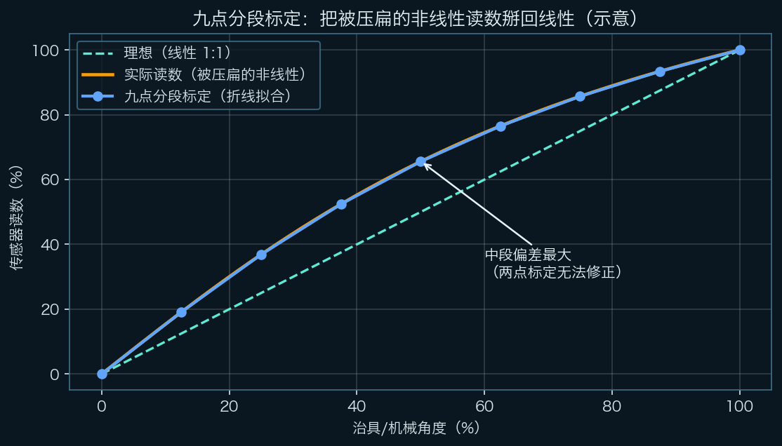
Two-point calibration (fully closed / fully open) can only map linearly, and can't correct mid-range non-linearity (a squashed curve isn't a straight line). So we added nine-point piecewise calibration in the application layer: the fixture supplies nine (fixture angle, raw value) pairs, and piecewise linear interpolation bends the non-linearity back.
Two Calibration Modes Coexist
Both sets of data are kept, and a mode field decides which one is active (whichever ran last wins):
| What you do | Active mapping |
|---|---|
| Nine-point "confirm calibration" | piecewise linear (points) |
| "Calibrate closed/open" | two-point linear (two-point) |
| The "enable nine-point calibration" button | explicitly switches back to piecewise |
Steps (web UI "Sensor" page)
- Put the finger in a fixture detent (say 20°) → click the matching button (averages over 2 seconds) → clicking a point again overwrites it
- Once all nine are in (
9/9 已采集) → click "confirm calibration" (checks: all nine present + readings monotonic with angle) - Once active it shows the opening percentage (the interface for the algorithms), the calibrated angle and the range in real time
Endpoints: /api/v1/angle/calib (GET/POST), /calib/{point,commit,reset,mode}, /angle/regress.
Readout Conventions (Easy to Mix Up)
| Display | Meaning |
|---|---|
| Live | the chip's raw angle (0–360°) plus raw, independent of calibration |
| Calibrated angle | the fixture angle (0–40°) that raw maps to under the current calibration; out of range shows ⚠超程 |
| Opening | the percentage that raw maps to under the current calibration (for the algorithms) |
| Range | the current calibration's range = span_raw / span_deg (chip angle) |
Convention gotcha: the endpoint fields (
closed_deg/open_deg/span_deg) are always chip angles, not fixture angles — the nine-point confirm used to write fixture angles into the endpoint fields, which made "range" show as 40°; that's now fixed everywhere.
Lessons and Pitfall Archive
| Symptom | Root cause | Diagnostic / fix |
|---|---|---|
| Huge unit-to-unit range spread, random direction | wrong magnet (axially magnetized) | switch to diametrical magnetization; check the magnetization direction per datasheet §8 on incoming goods and at assembly |
Readings pinned at 0x7FFFFF (359.99996°) | the sensor isn't responding (unpowered / unconnected / dropped out) and the MISO pull-up reads all ones | a real value near 360° jitters by a few LSB, so a pinned value is fake; check power and the J57 connection; the driver should add CRC/error-bit validation |
| Readings jump randomly across the full range (a few ms, ±300°) | no magnet, or the magnet isn't in place (bare board) | this isn't "noisy", it's no signal; fit the magnet |
| The percentage after calibration is astronomical | both samples were taken at the same position, so the endpoint span degraded | a 2000-raw guard is in place; recalibrate at two genuinely different positions |
| The two-point panel shows "range" as 40° | fixture angles were written into the endpoint fields | endpoint fields are now always chip angles |
Running tmr3109 alone from MSH trips an assertion | SPI was never initialised on its own | run angle_init first |
| Nothing changed after deploying | the docker cp of the build output was missed, so an old binary got pushed | always md5-compare the on-board binary against the build output |
| Noise at rest | a healthy unit has std ≈ 0.001° (~18 LSB) | above 0.5° check for mechanical wobble or field problems; measure noise by reading shared memory directly and de-duplicating by timestamp — HTTP polling double-counts and understates it |
Reproduction and Sources
| Item | Location |
|---|---|
| Driver | MCU: rtos/components/angle_sensor/angle_sensor.c (SPI Mode 1, bit extraction with the 4-clock delay correction) |
| Sampling | MCU: applications/gripper/sensor_acq.c (50Hz → shared memory) |
| Calibration | AP: app/gripper/v2/cmd/gripper-app/angle_calib.go, angle_calib_http.go, web/index.html |
| Datasheet | MultiDimension TMR3109 product datasheet v1.0.1 (§3.6 magnetic field specs, §4.1 SPI, §8 mechanical angle direction) |
| Knowledge base | Team skills: magnetic-angle-sensor, rv1126b-gripper-angle-calib |
Written 2026-09 · based on measurements from the gripper project · all data from real hardware